GNSS RECEIVERS
How They Work and The Best Ones On The Market
What Is A GNSS Receiver?
These days completing jobs as fast, accurate and error free are paramount for Construction, Survey and Civil companies.
A reliable GNSS Receiver is an essential tool for any construction site you can finish your surveys sooner and with greater precision by leveraging the power of the constellations and their accuracy.
Understanding what your instrument can and can’t do before you get started is crucial. On the plus side, you don’t need intervisibility between points. GPS works 24/7 in almost any weather and gives extremely geodetically accurate results. Best of all, you can get more done in less time with fewer people. At the same time, be aware of GNSS receivers limitations.
GNSS Limitations
Even though GNSS Receivers are amazing and can make a huge difference to the accuracy, speed and confidence of a job there are also some very obvious and detrimental limitations to this kind of technology.
Line Of Site (LOS)
One of the Limitations of GNSS Receivers is the fact that each receiver needs Line Of Site (LOS) to the constellation satellites. This make using a GNSS Receiver in a heavily covered area, Indoor or in really bad weather conditions causes GNSS Receivers to receiver low quality data.
Constellation Connection
To receive quality data your GNSS Receivers are required to connect to constellations. There are 5 different constellations based all over the world these are; GPS, GLONASS, BEIDOU, QZSS & SBAS. Some receivers only have the ability to connect to certain constellations, having the ability to connect to more constellations will mean more satellites are connected and your data is more accurate and reliable.
Receiver Quality
On the market today there are hundreds of different brands out there, they vary in price drastically. From your big name brands such as; Leica, Trimble, Topcon, Spectra Precision, CHC & Unistrong to your many lesser well known brands from around the well. Each GNSS Receiver they produce have different specifications. From high quality boards, Quality antennas, Rugged housings and Battery life all determine the quality of a GNSS Receiver. When it comes to purchasing a GNSS Receiver these attributes all play a part in the quality of GNSS Receivers.
Different Forms Of Measuring
When using a GNSS Receiver there are various different ways of measuring data. Static Measuring, Rapid Static Measuring, Kinematic Measuring, and RTK Measuring are all viable options depending on what application you are using them in. When it comes to using GNSS Receivers there are many different ways of producing accurate results but knowing which way of measuring is paramount to getting the right data for your job. If you use the wrong form of measurement then your data could be completly wrong, below is a breakdown of each form of measurement.
Static Measuring
Static measuring is the original GPS surveying technique. To measure a long baseline (20 km/16 mi and up), place the reference receiver at a known point. Next, place a second receiver (called the “rover”) at the other end of the baseline. Then, set identical data recording times – usually 15, 30, or 60 seconds – and measure for at least one hour. Depending on how long the line is, how many satellites are in sight, and their relative geometry, you may need to measure for a longer time. Remember: measure twice to avoid mistakes. Once you collect enough data, turn off the rover, move it to the next baseline, and repeat the process. For even greater speed, add another rover and alternate the two rovers’ placement to measure each line.
Rapid Static Measuring
If you’re working on a site that’s never had any GPS surveys done, you’ll first need to establish several points with known coordinates in order to calculate transformations. Choose a point for the reference receiver, then move one or more rovers to each of the other known points. As in static measurement, the time that each rover must measure depends on the baseline length and the GDOP. After you send the data to your office for processing, check for errors by measuring the same points again at a different time of day.
Kinematic Measuring
Set up the reference receiver, then place the rover at the end of the baseline. Making sure not to move the instruments from their stationary positions, turn on both receivers and wait 5 to 20 minutes (depending on the number of visible satellites and the baseline length). After the data is acquired, you can walk with the rover. It’s possible to record positions at a predefined rate, at predetermined positions, or both. However, try to avoid objects that might block the receiver signal. Should the rover lose sight of receivers so that there are fewer than four, move it to where it can see four or more satellites, then re-initialize it before you continue measuring.
Real-Time Kinematic (RTK) Measuring
RTK is replacing kinematic measuring. The rover gets signals from the reference, but because it also has its own GPS antenna, it receives satellite signals directly instead of through the reference receiver. The rover then processes both signals to resolve the ambiguity. Start by setting up the reference receiver. Once it is picking up the satellite signal, you can turn on the rover. Wait until the rover starts tracking both the satellites and the reference. When this happens, the rover will initialize, resolve ambiguities, and be ready to record both points and coordinates. Baseline measurements are accurate between 1 cm and 3 cm. Be sure not to lose contact with the reference, which causes the rover to lose the ambiguity calculations and thus accuracy. Check your transmitting radio for interference. Make sure the antennas on both the transmitting and receiving radios aren’t blocked by tall buildings, and that your cable to the antenna isn’t so long that the signal degrades.
Accuracy Case Study
To demonstrate the differences that can occur in GNSS Receivers due to connectivity between constellations and the internals of receivers we decided to undertake a project to determine the amount of drift certain receivers within our fleet undergo when used in an obstructed area.
Introduction
Spatial professionals of all types have a personal preference when it comes to their GNSS Systems. A lot of the time these decisions are based on the accuracy of these units. Cody Corporation has always aimed to dispel myths and legends when it comes to the surveying field.
Recently we underwent an exercise to put our GNSS Fleet to the test and see what accuracies we were able to obtain from these units and from this data be able to decipher what each GNSS units’ capabilities are.
Our aim was to discover which unit had the least radius of drift whilst measuring in an obscured position. We would take all data acquired and average out the total number of points against each other to find out which GPS receiver would produce the best clustered results. The point of this test was to decipher which GPS units had the least amount of variation; this is important when looking to purchase a unit which is going to be used in obstructed areas.
Things such as Antenna Strength, Constellation Connection & technical specifications of the board are incredibly important when it comes to minimizing the amount of drift from each GNSS unit.
The test we undertook are far from a controlled experiment and were undertaken over 2 days during the same window of time at the same location to try and emulate the results as perfectly as possible.
As any expert within the surveying field would know using a GNSS system in an open unobstructed field is the ideal setting for these devices but as we all know these settings aren’t always obtainable and more often than not these devices are used in obstructed areas.
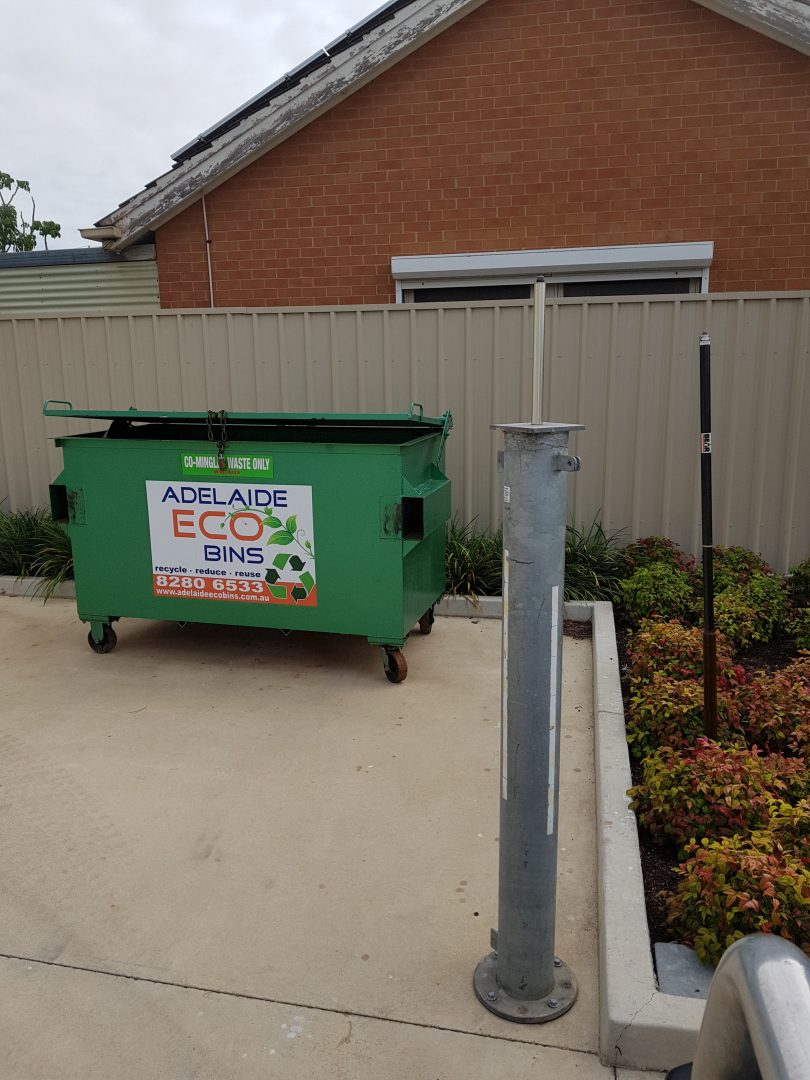
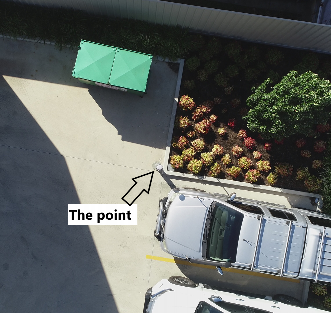
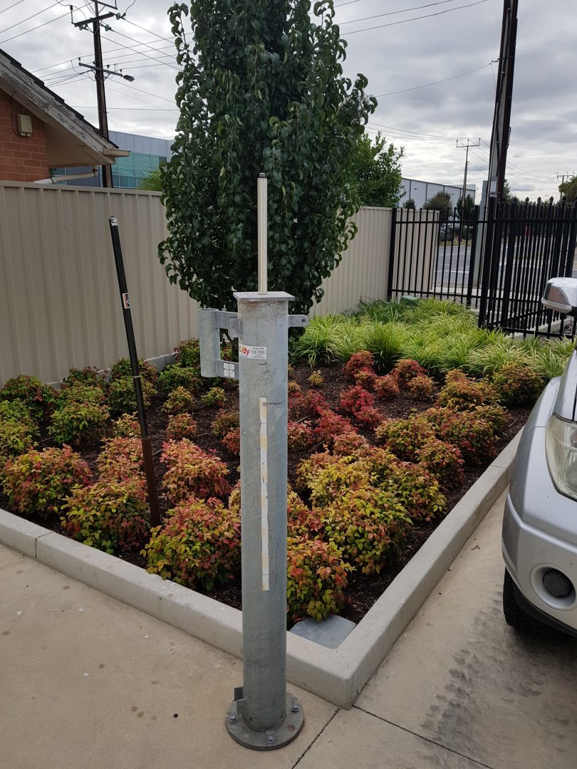
Our testing of these devices was done in an obscured area the 1 thing we made sure we had for this spot was it was a GDA (Geocentric Datum of Australia) Point. This point was tested thoroughly previously, and the point data has been logged to Geoscience Australia as a known point.
Below are the logged coordinates for this point and this data will be the benchmark for all the testing we undertook.
| Name | Latitude | Longitude | Ellipsoidal |
| AUSPOS | 6137764.312 | 278793.578 | 10.638 |
As a basic rule of thumb when it comes measuring the accuracy of a GNSS unit, we decided along with the AUSPOS Position being known and recorded and the Data collected over 2 days during the same window of time to optimize satellite positioning that we would also take points from each device every second taking a total of 1500 points per device, this would equate to 25 Minutes of testing on each device. This would allow us to get consistent average reading across all of the units we tested and allow our data to be relied upon just like it would be out on a job site.
Each GNSS Unit was configured to our CodyRTK Correction signal network on the GDA54 2020 projection. By using a single correction signal for each GNSS, it allows us a more consistent reading from each device to be able to equally compare them against each other.
Below are the Models which were tested and the manufactures best possible accuracy in an open position.
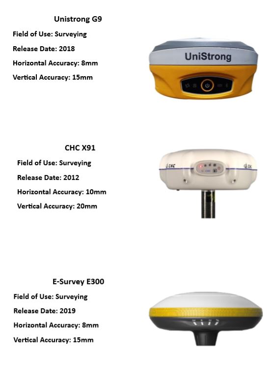
Not all GNSS Systems were able to track all constellations which caused a variation in the number of satellites available to draw data from. The Constellations that were tracked are as follows.
- Unistrong G9 – GPS, Glonass, BeiDou, Galileo, QZSS, SBAS
- CHC X91 – GPS, Glonass, BeiDou, Galileo, QZSS, SBAS
- E-Survey E300 – GPS, Glonass, BeiDou, Galileo, QZSS, SBAS
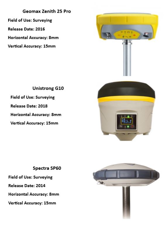
- Unistrong G10 – GPS, Glonass, BeiDou
- Spectra SP60 – GPS, Glonass, BeiDou
- Zenith 25 Pro – GPS, Glonass
RESULTS
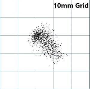
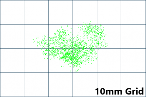
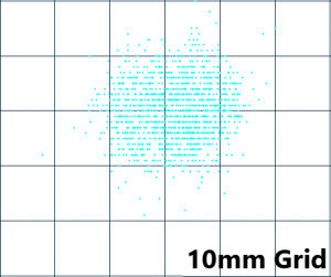
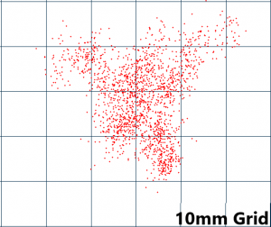
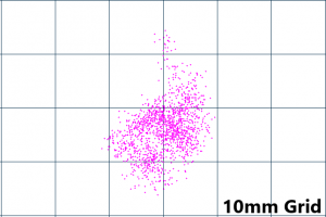
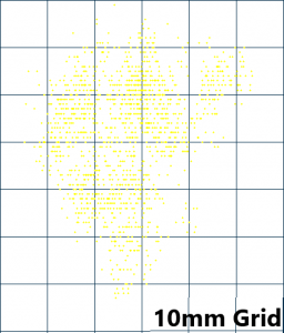
The positions calculated by each GNSS unit over the 1500 points allowed us to be able to get a quality reading on an obstructed known point and infer the results received as accurate data. As expected, it is clear that the accuracy and consistency of the calculated positions deteriorates near obstructions just like in real world scenarios.
After collating all the data below, it produces a clear image about what we were aiming to achieve. It is clear that accuracies and consistency of the calculated position deteriorates near obstructions, this happens to a different degree for each model.
When it comes to collating accurate data in an obstructed point having the best number of satellites to connect to, the strongest antenna signal and the most accurate board are all massive in ensuring the data receive is the best it can be.
| Model | North Variation | East Variation | Ellipsoidal Variation | Average Variation | Ranked Position |
| SP60 | 0.025 | 0.022 | 0.074 | 0.040 | 1st |
| G970 | 0.020 | 0.030 | 0.092 | 0.047 | 2nd |
| X91 | 0.039 | 0.042 | 0.089 | 0.057 | 3rd |
| G10 | 0.042 | 0.046 | 0.086 | 0.058 | 4th |
| E300 | 0.030 | 0.021 | 0.159 | 0.070 | 5th |
| Zenith25 | 0.062 | 0.048 | 0.169 | 0.093 | 6th |
Spectra SP60 GNSS Receiver
The Spectra SP60 in this test is the GNSS unit which had the least amount of drift associated to its results. This is a strong and reliable unit which is manufactured with a Trimble Board and has the best antenna out of all the GNSS units tested. The Z-Blade technology made a huge difference to the Ellipsoidal accuracy compared to all of the other units.
In summary the SP60 performed the best had the best North & East variation and Ellipsoidal Variation and was connected to the 3 largest constellations making this GNSS unit an excellent choice when being used in an obstructed area.
| Model | North Variation | East Variation | Ellipsoidal Variation | Average Variation |
| SP60 | 0.025 | 0.022 | 0.074 |
0.040 |
Unistrong G970 GNSS Receiver
The G970 performed amazingly well compared against the other systems, although it did not beat the SP60 overall with its results it was awfully close. With an excellent antenna, a Hemisphere Board and connectivity to all constellations this makes the G970 an excellent GNSS unit to have.
The biggest selling point to this particular unit is its incredibly low price point in comparison to other well-known brand-named units. It was able to perform very well at a fraction of the cost of a Spectra GPS Receiver this is something to keep in mind. If your looking for a unit to perform well in built up areas and your budget is unable to afford a brand-named unit then the G970 is an excellent choice.
|
Model |
North Variation |
East Variation |
Ellipsoidal Variation |
Average Variation |
|
G970 |
0.020 |
0.030 |
0.092 |
0.047 |
CHC X91 GNSS Receiver
The CHC X91 is an older GNSS unit but has been around for a long time and is a highly dependable and trusted unit amongst surveyors. For it to perform so well in this test only highlights why CHC is such as well known and trusted brand name in the industry. With its ability to connect to all constellations this aided the unit in providing decent results across the board. Its North & East variation was particularly good, and its Ellipsoidal variation was right in the middle of all the tested units.
For a unit which has been around a long time and technically has the least accurate board from the manufacturer it shows attention to detail from the manufacture makes a difference when presenting results. If you have one or have used one of the units over the years you will know firsthand the reliability of the CHC brand. If you are looking at upgrading to a new receiver then the first 2 units are clearly better units in this application but for the age of the receiver it performed quite admirably.
|
Model |
North Variation |
East Variation |
Ellipsoidal Variation |
Average Variation |
|
X91 |
0.039 |
0.042 |
0.089 |
0.057 |
Unistrong G10 GNSS Receiver
The Unistrong G10 is an excellent alternative to the CHC X91, its internals are very much the same as the CHC, both are running Trimble boards and with an upgraded Antenna it means the G10 provides results remarkably close to the X91. The G10 connects to the 3 major constellations which provide it with excellent signal strength. With the testing done the G10 was able to match the X91 North & East variation and actually beat the X91 in relation to Ellipsoidal Variation. Considering the CHC X91 is an obsolete model and unable to be purchased new anymore this makes the G10 the perfect successor to the CHC X91 on the market.
Similar to the G970 the Unistrong G10 comes in at a fraction of the price you would pay for the CHC and Spectra units making this unit an excellent choice. Primarily this unit has been used in the construction field with great success, an excellent housing makes it excessively rugged and durable out in the field.
|
Model |
North Variation |
East Variation |
Ellipsoidal Variation |
Average Variation |
|
G10 |
0.042 |
0.046 |
0.086 |
0.058 |
E-Survey E300 GNSS Receiver
As a benchmark for the lower end of the market we used the E-Survey E300 which is their newest GNSS Receiver they supply. It has an incredibly low cost associated to it and with that low-end cost it does have some obvious draw backs. Although its North & East variations were quite good and on par with the other tested results it was the Ellipsoidal Variation which really let down the E300. As a unit which mainly serves the lower end of the GPS Price Market it performed as well as predicted.
If you’re in the market for a GNSS Unit and you’re working within a very tight budget this unit can be used to perform some basic GNSS Applications but in regard to using it for highly important and accurate work we would advise with spending a bit more money and going with either the G10 or G970 as alternatives which provide greater accuracy and durability.
|
Model |
North Variation |
East Variation |
Ellipsoidal Variation |
Average Variation |
|
E300 |
0.030 |
0.021 |
0.159 |
0.070 |
Geomax Zenith 25 GNSS Receiver
Finally, the Geomax Zenith25 is the unit which produced the biggest variation on results. These results can be attributed to the fact it is only able to connect to the GPS & GLONASS constellations giving it extremely limited number of satellites to call upon. As we highlighted earlier the ability to connect to as many satellites as possible will always help when trying to produce the most accurate results. The Zenith25 may have performed much better should it have the ability to connect to more constellations. All the other features of the Zenith25 are excellent and make a great GNSS Unit in theory but when accuracy is everything in this field of work having an inability to open up to all constellations leans you towards purchasing the Geomax Zenith25’s additional extras. This allows you access to further constellations and after seeing the results derived from this test we would highly advise this option.
If you were contemplating purchasing the Zenith25 you should have a look at the Spectra SP60 again and notice the results, features and similar price point to the Zenith25 and this alone should be enough to highlight the Zenith25’s pitfalls.
|
Model |
North Variation |
East Variation |
Ellipsoidal Variation |
Average Variation |
|
Zenith25 |
0.062 |
0.048 |
0.169 |
0.093 |
CLOSING
As with all Equipment Cody Corporation supplies, we are totally independent and only provide the best units for the customer and the job on hand. In light of all these units which we tested there are other things we would advise out in the field which would provide you with an increase in your accuracies on-site.
Local Area Site Calibration
By tying in your GPS to the site your working on this will aid in giving your GNSS the best chance of producing the most accurate results possible.
RTK Correction Signal
Making sure you have a strong and reliable RTK correction signal aids in producing you with accurate results no matter what site you are working on. When using an RTK Correction Service making sure you are accessing the closest base is always a must as well as this will provide you with the best.
Future Testing
Should you wish for us to test some other GNSS Receivers please contact us here at Cody Corporation and we will arrange a time to test other units. Just like you we like to know how each individual unit performs against another.