Automatic Level Compensators
Automatic levels have been with us since the middle of the twentieth century. Today, they are so common place that the adjective “automatic” is frequently not even used. But this advance in technology has been the single most significant feature in the history of vertical distance measurement.
The basic principle of optical levelling is to create a line of sight through the telescope that is normal to the direction of gravity at that point (i.e. horizontal). Before automatic levels, this was done by ensuring that the vertical axis of the level (i.e. the axis of rotation) was truly vertical. Other adjustments ensured that the line of sight was perpendicular to this vertical axis. The basic advance of the automatic level is that the level of perfection in verticality of the axis is no longer critical.
Even with well-made pre-automatic instruments, ensuring that the axis was vertical had practical limitations, thus requiring the surveyor to re-level the instrument with every sighting. The practical problem resolved for the surveyor is that this revelling is no longer necessary.The technology in the instrument “automatically” does it.
Products Sold Today
Today on the market there are a variety of Automatic Levels which can be purchased for alot of construction jobs.
The Technology
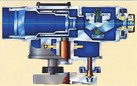
The compensator of an automatic level uses gravity to suspend or balance a portion of the instrument optics. In this way, the optical path of light through the instrument is compensated for the vertical axis error before reaching the user’s eye. Different manufacturers, in various products and at different times, have implemented many different designs. However, certain fundamental principles and components remain common: the optical system, suspension system, and damping system.
Optical System
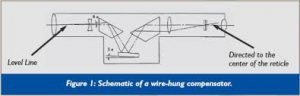
In addition to the basic telescope lens elements, the light entering into the objective lens of the instrument must pass through a mechanical compensator system before reaching the user’s eye. Most compensators include mirrors and/or prisms to direct the light through the compensator. The effect of passing the light through the compensator is to alter the reading at the reticle so as to be corrected for the level error.
The compensator optical components shown in Figure 1 in schematic form depict a mirror suspended from fine wires like a pendulum to compensate for levelling error. Many modern instruments actually use a prism for the moving element.
Suspension System
Because compensator systems rely on a suspended optical component to establish the level line automatically, the suspension systems must support the movable optical component in as friction-free manner as possible. Any binding in the suspension will cause the system to come to rest prior to seeking a true horizontal line. The most common suspension system today is the wire-hung type. Other types that have been used in the history of automatic levels include Mylar tapes instead of wires, ball bearings, and magnetically levitated compensators.
Damping Systems
A damping device quickly stops the suspended component from swinging indefinitely. Without a damper, the suspended portion of the compensator could swing for quite some time (like a pendulum) before settling down enough to allow the user to read the rod. The user would see the cross-hair bouncing up and down. Because of the damping device, the compensator will normally stop moving before the user even looks through the telescope to focus on the rod. While the damping system also assists in resisting sudden quivering type movement caused by wind or vibration, it is also possible for a frequency or amplitude to be reached that makes a stable line of sight impossible. Technology for damping is quite often magnetic. However, pneumatic or air damping is also used. They both have their advantages and neither has been shown to be superior to the other.
Limitations and Errors
As with all technologies, optimum use is enabled by understanding how the technology works, knowing its limitations, and possessing the skills for evaluating, calibrating, and adjusting it. A few of these are now briefly mentioned here.
Compensation Range
Automatic level compensators only work within a certain amount of tilt of the vertical axis, called the compensation range. The exact range varies between different models but is often 10 to 20 arc-minutes. If you are outside of the compensation range, the suspended assembly in the compensator will simply “bottom out” against its physical maximum swing limit. Insuring that the instrument is levelled with a well adjusted bulls eye bubble best eliminates this problem.
Curvature & Refraction
Automatic level compensators seek a horizontal line of sight through the telescope. There is no way for the compensator to correct for earth curvature and atmospheric refraction. The best procedure is to simply limit your observations to approximately 100 meters so that the errors are relatively insignificant.
Shock
Level compensators use delicate suspension systems to accurately align the line of sight. Although designed for use in field conditions, a well-informed user is assumed. Excessive shock can harm the compensator or cause the instrument to fall out of calibration.
Vibration
Damping systems help, but severe vibrations cannot be overcome. The problem will be evident when you literally see the cross-hairs vibrate up and down while trying to read. Vibration can also be a problem in storage and transport as well. If the instrument is subject to excessive vibration, it can drift out of calibration.
Errors
Errors generally fall into two categories. The first is error caused by a malfunctioning compensator. The second is calibration error. The user should read the instrument’s manual carefully to understand how to determine (frequently) whether these types of errors are present. Your authorised instrument repair station can also help you with understanding these errors, diagnosing them and, if desired, adjusting the instruments. Illustrations courtesy of Nikon
Head over to the Automatic Level page and have a look at our range of Automatic Levels.